Last updated: October 7, 2026
How to Wire a DC-DC Charger: The Short Answer
To wire a DC-DC charger in a van, you run a fused positive cable from the starter battery to the charger’s input, connect the charger’s output to the house battery’s positive bus (with another fuse within 7 inches of the bank), ground both sides to a common negative bus or chassis point, and run a small ignition or D+ trigger wire so the unit only charges while the engine runs. The whole job takes most DIYers 3-5 hours with basic tools, and the details below cover fuse sizing, cable gauge, and smart alternator triggers for a typical 20-60A installation.
What a DC-DC Charger Does (and Why a Relay Isn’t Enough)
See also: How Long Will a 100Ah Battery Last in a Van? Runtime Math Explained • Best Level 2 EV Chargers for Home
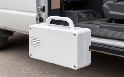
A DC-DC charger – also called a battery-to-battery (B2B) charger – sits between your starter battery and house bank and converts the alternator’s output into a proper multi-stage charging profile for lithium, AGM, or gel batteries. Unlike a simple split-charge relay, it boosts low voltage (common on Euro 6 smart alternators that drop to 12.3V), limits current so a hungry lithium bank can’t overload the alternator, and isolates the two batteries when the engine is off. Popular units in 2026 include the Victron Orion-Tr Smart (18A and 30A), Renogy’s 20/40/60A chargers, Redarc BCDC series (25A, 40A, 50A), and Sterling Power BB1260.

BOJACK 2pcs 100A ANL Fuse Holder and 2pcs 100Amp 32VDC ANL Fuses for Audio and Video Systems
Included for 'How to Wire a DC-DC Charger in a Van (Diagram + Fuse Sizes)' as a relevant option in this category; details come from the product listing.
View on Amazon
BOJACK 0/2/4 Gauge AWG in Line ANL Fuse Holder with 100 Amp Fuse
Included for 'How to Wire a DC-DC Charger in a Van (Diagram + Fuse Sizes)' as a relevant option in this category; details come from the product listing.
View on Amazon
SIGANDG 0/2/4 Gauge AWG Inline ANL Fuse Holder with 100 Amp Fuse
Included for 'How to Wire a DC-DC Charger in a Van (Diagram + Fuse Sizes)' as a relevant option in this category; details come from the product listing.
View on Amazon
Shirbly 4 Gauge Battery Cable, 10FT Red + 10FT Black 4 AWG Pure Copper Wire Welding Cable, for Automotive, Battery, Solar and Generator, Standard USA OFC Wire
Included for 'How to Wire a DC-DC Charger in a Van (Diagram + Fuse Sizes)' because the listing specifies 10FT Red + 10FT Black 4 AWG Pure Copper Wire Welding Cable and for Automotive, details this guide uses to compare options.
View on Amazon
iGreely 4 AWG Gauge Wire Pure Copper Welding Battery Cable for Vehicle Solar,10Ft Black+10Ft Red Flexible OFC Cables with 5pcs of 5/16"" & 5pcs 3/8"" Copper Lug Terminal Connector Heat Shrink Tubing
Included for 'How to Wire a DC-DC Charger in a Van (Diagram + Fuse Sizes)' as a relevant option in this category; details come from the product listing.
View on AmazonDC-DC Charger Wiring Diagram (Text Version)
The full run looks like this:
- Starter battery (+) → main fuse (within 18 cm / 7 in of the post) → 6-4 AWG cable → charger INPUT (+)
- Starter battery (−) or chassis ground → same-gauge cable → charger INPUT (−)
- Charger OUTPUT (+) → fuse or breaker near house bank → house busbar / battery (+)
- Charger OUTPUT (−) → house negative busbar (not the chassis, ideally – shunt-based monitors need everything on the bus)
- Ignition/D+ wire (18-16 AWG) → charger trigger terminal
- Temperature sensor / remote lead → battery negative terminal (if your unit supports it)
Mount the charger as close to the house bank as practical – the output side carries the regulated current, so a long input run with thicker cable loses less than a long thin output run.
Step-by-Step DC-DC Charger Installation
1. Disconnect both battery negatives first. Always work dead – a dropped wrench across a starter battery terminal will weld itself in place.
2. Pick the mounting location. Chargers get warm under load (most derate above 40°C), so mount vertically on a ventilated wall or seatbox, not flat under carpet or inside a sealed cabinet. Keep total cable runs under about 5 m if possible.
3. Run the input cable. Route positive and negative together through grommets wherever they pass through metal. In most vans there’s a factory grommet near the driver’s seat or behind the dash into the engine bay. Seal any new holes with silicone.
4. Fuse the input at the starter battery. Use a MIDI, ANL, or MEGA fuse holder bolted within 18 cm of the positive post. This fuse protects the cable, not the charger – size it to the wire.
5. Fuse the output near the house bank. Same rule: within 18 cm of the positive busbar or battery terminal.
6. Wire the negatives. Run dedicated negative cables rather than relying on chassis ground where possible – chassis returns through rusty body seams are the number one cause of “my charger keeps dropping out” complaints. If you must ground to the chassis, sand to bare metal, use a proper ring terminal and star washer, and coat with dielectric grease.
7. Connect the trigger wire (see the smart alternator section below), then connect the temperature sensor to the house battery negative if supplied.
8. Set the battery profile. Before powering up, configure the charger for your chemistry – LiFePO4 typically wants 14.2-14.6V absorption and no float, AGM around 14.4V. On Victron and Renogy units this is done via app; Redarc auto-detects on some models.
9. Reconnect negatives, start the engine, and verify. You should see input voltage around 13.5-14.4V and rated current flowing to the house bank within a minute of startup.
Fuse and Wire Sizing Chart
Two numbers matter: the charger’s rated output amps, and the input draw, which is roughly 20-30% higher because the unit boosts voltage. A 40A charger pulls about 50A from the alternator. Cable sizes below assume a 12V system, 3% max voltage drop, and a one-way run of up to 4 m – go one size thicker for longer runs.
| Charger rating | Input fuse (at starter battery) | Output fuse (at house bank) | Cable gauge (≤4 m run) | Typical examples |
|---|---|---|---|---|
| 18-20A | 30A | 25-30A | 6 AWG / 16 mm² | Victron Orion-Tr Smart 12/12-18, Renogy 20A |
| 25-30A | 40-50A | 40A | 6 AWG / 16 mm² | Victron Orion-Tr 30A, Redarc BCDC1225D |
| 40A | 60A | 50-60A | 4 AWG / 25 mm² | Redarc BCDC1240D, Renogy 40A |
| 50-60A | 80A | 70-80A | 2 AWG / 35 mm² | Renogy 60A, Sterling BB1260, Redarc BCDC1250D |
Undersizing the input fuse causes nuisance blows at high alternator load; oversizing it means a shorted cable becomes a fire risk. Also check your alternator’s spare capacity – a 60A charger on a small 130A alternator that’s already running headlights, A/C, and heated seats can push it into early failure. Many installers cap lithium charging at roughly 30-40% of alternator rating.
Ignition vs D+ Trigger on Smart Alternators
Modern vans with Euro 5/6 smart alternators don’t output steady voltage, so old-school voltage-sensing relays fail. Your DC-DC charger needs one of these triggers:
- D+ terminal: Older Mercedes Sprinters and some Ducatos have a dedicated D+ alternator output pin – the cleanest option if your van has it.
- Ignition-switched 12V: Tap a fuse-slot that’s live only with the key on (an add-a-fuse on the wiper or seat fuse works). This is what most 2026 builds use.
- Built-in voltage sensing: Victron Orion-Tr Smart and Redarc BCDC units can detect engine running from input voltage alone – no trigger wire needed, but disable this if your starter battery is charged by a second alternator or external charger that could create a loop.
- CAN/Linbus signal: Some newer vehicles need a signal interface rather than a raw D+ tap – check your van’s upfitter documentation (Ford, Mercedes, and Stellantis all publish body-builder wiring guides).
Mistakes That Kill These Installations
- Fuse in the wrong place. The input fuse belongs at the battery post, not at the charger – an unfused 4 m cable run through the engine bay is the classic van-fire scenario.
- Chassis-only negative on lithium setups. Voltage drop on corroded returns makes lithium chargers hunt on and off. Run the dedicated negative.
- Wrong charge profile. Leaving a charger on “lead acid” for a LiFePO4 bank gets you to 80% state of charge and no further – the most common “my battery never fills” complaint.
- Square terminals on round cable. Crimp lugs with a proper hex or indent crimper and heat-shrink every joint; insulation-displacement and hand-crushed connectors work loose on corrugated roads.
- No airflow. A 60A charger dissipates real heat; units mounted inside sealed seatboxes thermally derate to half output in summer.
Quick FAQ
Can I wire a DC-DC charger without a second fuse on the output? Technically it will work, but any short between the charger and house bank is then unprotected – always fuse within 18 cm of the battery.
Do I still need one with a smart alternator? More than ever – smart alternators deliberately undercharge, so a lithium bank on a relay alone may never reach full charge.
What size charger do I need? Match roughly 20-30% of your house bank’s amp-hours (a 200Ah lithium pair pairs well with a 40-60A unit) and stay within your alternator’s spare capacity.